Yesterday, I managed to put together the in-class demo I discussed previously. In this post I’d like to give a brief explanation of what I showed and how it demonstrates the proper use of SystemVerilog to describe a finite state machine (FSM).
What I saw many students doing in their 3rd lab, was to use an English language description of the behavior they wanted that they translated directly to behavioral SystemVerilog. This is a fundamentally different procedure than I had intented to teach in the class, which was to take the English description of the behavior they want, and translate it to a FSM. The next step is to use that FSM and describe it using a standard SystemVerilog implementation. This includes 2 pieces of combinational logic, and a single sequential state register.
For this finite state machine, I describe what happens to a student when he or she sleeps. First, let’s say that a student can be happy, very happy, unhappy, or very unhappy. Whenever that student sleeps, happiness increases until it saturates at very happy. If a student doesn’t sleep, then happiness decreases until it is empty at very unhappy. When the student is happy, or very happy, the student will smile. The following examples are implementations of this description.
The first thing I showed in my demo is the following behavioral description based on the English description:
 1module student_beh (input logic sleep, clk, output logic smile);
 2
 3logic [1:0] happiness;
 4
 5initial happiness = 2'b10;
 6
 7always_ff @(posedge clk) begin
 8	if (sleep) begin
 9		if (happiness < 2'b11) // if sleeping not fully happy, increase happiness
10			happiness = happiness + 2'b01;
11	end
12	else begin
13		if (happiness > 2'b00) // if not sleeping decrease happiness
14			happiness = happiness - 2'b01;
15	end
16
17	if (happiness >= 2'b10) begin smile <= 1; end // when happy, smile
18	else  begin smile <= 0; end
19end
20endmodule
21
This module synthesized into the following RTL circuit diagram:
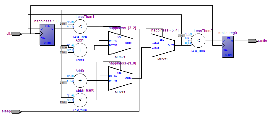
The next implementation I displayed uses a traditional FSM description in SystemVerilog:
module student_fsm (input logic sleep, clk, output logic smile);
typedef enum logic [1:0] {VU, UU, HH, VH} statetype;
statetype state, nextstate;

always_ff @(posedge clk) // State register
	state <= nextstate;

always_comb // next state logic
	case(state)
		VU:	nextstate = sleep ? UU : VU;
		UU:	nextstate = sleep ? HH : VU;
		HH:	nextstate = sleep ? VH : UU;
		VH:	nextstate = sleep ? VH : HH;
		default: nextstate = HH;
	endcase

assign smile = (state == HH | state == VH); // output logic

endmodule
This module syntheizes into a much nicer looking FSM as shown:
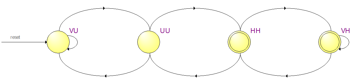
The first synthesis results sorta resemble an FSM, but are prone to bugs and inconsistent behavior, and led many students to spend much more time than they should have on the first lab assignment. The second synthesis results show exactly an FSM, and if we translated our English to an FSM diagram before starting to code, then we will easily be able to match our FSM to the results. The second technique is very much preferred for any hardware design.